Combinational vs sequential — the mental model that unlocks RTL
Every digital design is built from two kinds of logic: combinational (outputs depend only on current inputs) and sequential (outputs also depend on stored state updated by a clock). Mixing them up is the #1 beginner RTL bug.
If you remove the clock and the circuit still has a defined output from inputs alone → combo. If it “remembers” → sequential.
Picture the difference
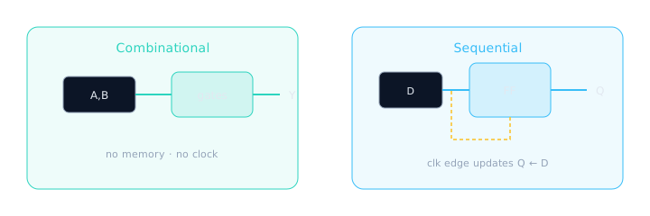
Combo = cloud of gates. Sequential = flops that sample on a clock edge.
Combinational syntax in Verilog
Two common styles: continuous assign, and always @(*) (combinational always). Both must assign outputs for all input combinations or you infer a latch.
- assign — one expression per wire; best for simple logic.
- always @(*) — if/case trees; every path must assign every output.
- Sensitivity
@(*)re-runs when any input changes (combo behavior).
module combo_mux_add (
  input  wire [3:0] a, b,
  input  wire       sel,
  output wire [3:0] y_mux,
  output wire [4:0] y_sum
);
  // Continuous assign — pure combo
  assign y_mux = sel ? b : a;
  assign y_sum = a + b;          // 5-bit result intentional

  // Equivalent mux with always @(*)
  // reg [3:0] y2;
  // always @(*) begin
  //   if (sel) y2 = b; else y2 = a;
  // end
endmodule
| Construct | Use when |
|---|---|
assign y = …; | Simple expressions, one driver |
always @(*) begin … end | if/case trees; use blocking = |
| Incomplete case/if | Bad — latch inferred (unintended memory) |
Latch trap: If an always @(*) path forgets to assign a signal, synthesis builds a latch so the old value is remembered — combo that secretly became sequential.
// BAD — y not assigned when en=0 → latch
module latch_bad(input en, input [7:0] d, output reg [7:0] y);
  always @(*) begin
    if (en) y = d;
    // missing else → latch!
  end
endmodule

// GOOD — always assign
module latch_good(input en, input [7:0] d, output reg [7:0] y);
  always @(*) begin
    if (en) y = d;
    else    y = 8'd0;   // or y = y_hold from a flop elsewhere
  end
endmodule
Sequential syntax — the flip-flop template
Edge-triggered storage uses always @(posedge clk …) and non-blocking <= assignments.
module seq_reg (
  input  wire       clk,
  input  wire       rst_n,   // active-low async reset (common)
  input  wire [7:0] d,
  input  wire       en,
  output reg  [7:0] q
);
  always @(posedge clk or negedge rst_n) begin
    if (!rst_n)
      q <= 8'd0;
    else if (en)
      q <= d;            // sample D on rising edge when enabled
  end
endmodule
Sequential: Q follows D one clock later (registered).
| Rule | Why |
|---|---|
Use <= inside clocked always | Models parallel flop updates correctly |
Use = inside combo always | Immediate update within the block |
| Do not mix both carelessly | #1 simulation mismatch source |
Blocking vs non-blocking — simulation story
Inside a clocked always block, = (blocking) runs top-to-bottom immediately; <= (non-blocking) schedules all RHS reads first, then updates LHS at the end of the time step. Hardware flops update in parallel — so sequential logic should use <=.
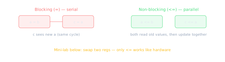
Blocking chains updates; non-blocking models parallel flop sampling.
Mini-lab — swap a and b on one clock edge
- Start:
a=8'hAA,b=8'h55. - On posedge, you want
a←bandb←asimultaneously. - Wrong (blocking):
a=b; b=a;→ both end up 0x55 (second line reads already-updated a). - Right (non-blocking):
a<=b; b<=a;→ a=0x55, b=0xAA after the edge.
// WRONG — blocking swap in clocked always
module swap_blocking_wrong (
  input wire clk,
  output reg [7:0] a, b
);
  initial begin a = 8'hAA; b = 8'h55; end
  always @(posedge clk) begin
    a = b;   // a becomes 0x55 immediately
    b = a;   // reads NEW a → both 0x55
  end
endmodule
// RIGHT — non-blocking swap (hardware-like)
module swap_nonblocking_right (
  input wire clk,
  output reg [7:0] a, b
);
  initial begin a = 8'hAA; b = 8'h55; end
  always @(posedge clk) begin
    a <= b;   // schedules a <- old b
    b <= a;   // schedules b <- old a (parallel)
  end
endmodule
| Context | Use | Assignment |
|---|---|---|
always @(*) combo | Immediate logic | = blocking |
always @(posedge clk) seq | Flops, registers | <= non-blocking |
| Testbench procedural | Stimulus ordering | = blocking (usually) |
Mixing = and <= in one clocked block creates race conditions that simulate differently from synthesis intent. Pick one style per always block.
Putting them together — RTL “recipe”
Classic pattern: compute next with combo, store with flops:
module counter_combo_seq (
  input  wire       clk,
  input  wire       rst_n,
  input  wire       en,
  output reg  [3:0] count
);
  wire [3:0] next = en ? (count + 4'd1) : count; // combo

  always @(posedge clk or negedge rst_n) begin   // seq
    if (!rst_n) count <= 4'd0;
    else        count <= next;
  end
endmodule
Combo is the kitchen cooking right now. Sequential is the fridge — it only updates when you open the door on the clock edge.
🎯 What to remember
- Combo: no clock, full assignment coverage, blocking
=. - Sequential: clock edge, non-blocking
<=, holds state. - Incomplete combo assignments → accidental latches.
- Blocking
=in clocked blocks → swap/shift bugs in simulation. - Next: clocks, edges, setup & hold intuition.