Clocks, edges, setup & hold (intuition first)
A clock is a periodic signal that tells flip-flops when to sample. Real silicon needs the data to be stable before (setup) and after (hold) the capturing edge — or the flop can go metastable / capture garbage.
Setup = arrive early enough before the bell. Hold = don’t yank the paper away too soon after the bell.
Clock edges and period
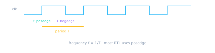
Rising edge (posedge) is the usual sampling event in synchronous RTL.
// Testbench clock generator pattern
module tb_clock;
  reg clk = 0;
  always #5 clk = ~clk;   // 10 time-unit period (toggle every 5)

  initial begin
    $display("Clock period = 10 time units");
    #100 $finish;
  end
endmodule
Syntax: always @(posedge clk) means “enter this block when clk rises.” #5 is simulation delay — not synthesizable for clocks in RTL; real clocks come from pads/PLLs.
Setup time — arrive before the edge
Data launched by one flop must travel through combo logic and be stable at the next flop’s D pin at least tsu before the capturing edge.
- Launch flop outputs Q on posedge.
- Signal propagates through gates (combo delay).
- Must arrive and stay stable before next posedge minus tsu.
- If delay > clock period − overhead → setup violation.
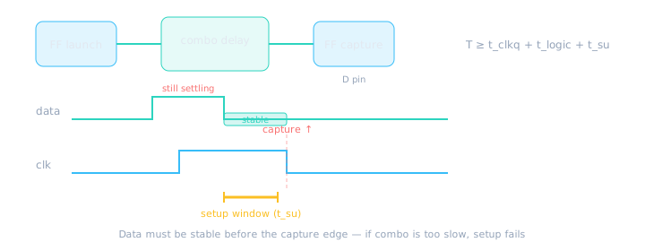
If logic is too slow for the period, setup fails (negative slack).
Giant combo clouds between flops eat the period. Pipeline (add flops) or simplify logic to fix setup — that is why registered outputs help.
Hold time — stay stable after the edge
After the capturing edge, D must remain stable for th. Hold failures happen when a new value races through too fast combo from the launching flop on the same edge.
Beginners meet setup more often in coursework. Hold is critical in real silicon — especially with fast local paths and clock skew.
Clock skew — same edge, different arrival time
Skew is the delay difference between clock signals reaching different flops. If capture clock arrives early relative to launch, the capture flop may sample before data is stable — a hold-time problem. If capture arrives late, you lose setup margin.
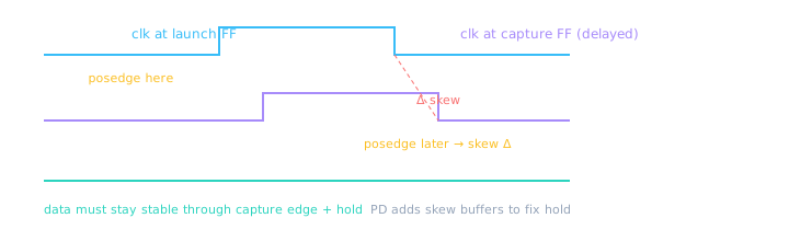
Skew shrinks the effective hold window — why “too fast” local paths worry PD engineers.
You rarely fix skew in RTL — but knowing it exists explains why hold fixes happen in layout, and why gating clocks locally is dangerous.
Multi-cycle paths — when one clock is not enough
Most paths are single-cycle: launch at edge N, capture at edge N+1. Some intentionally take multiple cycles — a slow divider, a wide multiplier, or a handshake FSM. Tools need to know or they will demand impossible timing on that path.
- Identify logic that by design cannot settle in one period.
- Register intermediate results (pipeline) — preferred in RTL.
- Or declare a multi-cycle path in constraints (ASIC SDC / FPGA XDC) — “capture may happen 2–3 cycles later.”
| Approach | RTL action | Constraint hint |
|---|---|---|
| Pipeline | Add flop stages; each stage meets 1-cycle timing | Standard 1-cycle paths |
| Multi-cycle exception | Keep long combo cloud; document intent | set_multicycle_path (SDC/XDC) |
| False path | Async reset, static config | set_false_path |
// Preferred RTL: break slow path with a pipeline flop
module pipeline_add (
  input  wire clk, rst_n,
  input  wire [15:0] a, b,
  output reg  [16:0] sum_r
);
  reg [16:0] sum_next;
  always @(*) sum_next = {1'b0, a} + {1'b0, b};  // combo (may be slow)

  always @(posedge clk or negedge rst_n) begin
    if (!rst_n) sum_r <= 17'd0;
    else        sum_r <= sum_next;   // registered → 1-cycle path to sum_r
  end
endmodule
// If you truly need 2 cycles, add another flop stage OR
// tell STA: set_multicycle_path 2 -from [get_cells sum_next*] -to [get_cells sum_r*]
Declaring multi-cycle paths without matching RTL behavior → silicon captures garbage on cycle 1. Pipeline first; constraints second.
Synchronous design rule
- One main clock per domain; flops share that clock.
- Do not use a derived gated clock casually — prefer clock enables.
- Crossing clocks needs CDC (later Module 9 + CDC course).
// Preferred: clock enable (same clk) instead of gating clk
module clock_enable (
  input  wire clk,
  input  wire rst_n,
  input  wire en,
  input  wire d,
  output reg  q
);
  always @(posedge clk or negedge rst_n) begin
    if (!rst_n) q <= 1'b0;
    else if (en) q <= d;   // gated by enable, not by AND on clk
  end
endmodule
Period is the schedule between trains. Setup is “be on the platform before departure.” Hold is “don’t leave your luggage on the tracks the instant the train starts.”
🎯 What to remember
- Posedge sampling dominates RTL style.
- Setup: data must arrive early enough (logic too slow → fail).
- Hold: data must not change too soon after the edge.
- Prefer clock enables over ad-hoc clock gating in RTL.
- Skew and multi-cycle paths affect real sign-off — pipeline when you can.
- Next: reset — why chips need a clean start.