1 / 2 / 3 always-block styles — pick one and master it
The same FSM can be written as one monolithic always block, two blocks (sequential state + combo next-state), or three blocks (state + next-state + output decode). All synthesize to similar hardware — the difference is readability, reviewability, and team consistency.
Pick 2-block (state reg + combo next) or 3-block (add output decode) and use it everywhere on your team. Avoid 1-block FSMs in production RTL except for tiny glue logic.
Three styles — structural map
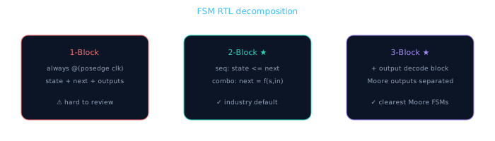
Same hardware, different code organization. Teams standardize on 2- or 3-block.
| Style | Blocks | Best for | Risk |
|---|---|---|---|
| 1-always | Single always @(posedge clk) | Tiny counters, teaching | Mixing combo + seq; incomplete defaults |
| 2-always | Seq state + combo next | Most control FSMs | Outputs buried in next-state if not careful |
| 3-always | Seq + combo next + combo/assign outputs | Moore FSMs with many outputs | Slightly more lines; clearest separation |
Reference FSM — byte-ready handshake
All three examples implement the same spec:
- IDLE: wait for
rx_valid - STORE: latch
rx_data, assertbyte_ready - WAIT_ACK: hold until
cpu_ack, return to IDLE
Style 1 — single always block (avoid in production)
// 1-block style — state, next, and outputs in one sequential block
module one_block_fsm (
  input  wire       clk, rst_n,
  input  wire       rx_valid, cpu_ack,
  input  wire [7:0] rx_data,
  output reg  [7:0] stored_byte,
  output reg        byte_ready
);
  localparam IDLE=2'd0, STORE=2'd1, WAIT=2'd2;
  reg [1:0] state;

  always @(posedge clk or negedge rst_n) begin
    if (!rst_n) begin
      state       <= IDLE;
      byte_ready  <= 1'b0;
      stored_byte <= 8'h00;
    end else begin
      case (state)
        IDLE: begin
          byte_ready <= 1'b0;
          if (rx_valid) begin
            stored_byte <= rx_data;
            byte_ready  <= 1'b1;
            state       <= STORE;
          end
        end
        STORE:  state <= WAIT;
        WAIT: begin
          if (cpu_ack) begin
            byte_ready <= 1'b0;
            state      <= IDLE;
          end
        end
        default: state <= IDLE;
      endcase
    end
  end
endmodule
Outputs and next-state are interleaved. Reviewers must mentally separate sequential from combinational intent. Lint tools may flag multi-driver risks if you refactor carelessly.
Style 2 — two always blocks (recommended)
// 2-block style — sequential state + combinational next-state/outputs
module two_block_fsm (
  input  wire       clk, rst_n,
  input  wire       rx_valid, cpu_ack,
  input  wire [7:0] rx_data,
  output reg  [7:0] stored_byte,
  output reg        byte_ready
);
  localparam IDLE=2'd0, STORE=2'd1, WAIT=2'd2;
  reg [1:0] state, next;

  // Block 1: state register
  always @(posedge clk or negedge rst_n)
    if (!rst_n) state <= IDLE;
    else        state <= next;

  // Block 2: next-state + output logic (Mealy-ish outputs here)
  always @(*) begin
    next        = state;
    byte_ready  = 1'b0;
    case (state)
      IDLE: if (rx_valid) begin
              stored_byte = rx_data;  // latch intent — see note below
              byte_ready  = 1'b1;
              next        = STORE;
            end
      STORE: next = WAIT;
      WAIT:  if (cpu_ack) next = IDLE;
             else byte_ready = 1'b1;
      default: next = IDLE;
    endcase
  end
endmodule
Note: For stored_byte, production code registers the latch in the sequential block. The 2-block pattern cleanly separates next computation; move data latching to Block 1 when outputs must be registered.
Style 3 — three always blocks (Moore outputs)
// 3-block style — state reg + next-state + output decode
module three_block_fsm (
  input  wire       clk, rst_n,
  input  wire       rx_valid, cpu_ack,
  input  wire [7:0] rx_data,
  output wire [7:0] stored_byte,
  output wire       byte_ready
);
  localparam IDLE=2'd0, CAP=2'd1, HOLD=2'd2;
  reg [1:0] state, next;
  reg [7:0] data_reg;

  // Block 1: state register + datapath register
  always @(posedge clk or negedge rst_n) begin
    if (!rst_n) begin
      state    <= IDLE;
      data_reg <= 8'h00;
    end else begin
      state <= next;
      if (state == IDLE && rx_valid)
        data_reg <= rx_data;
    end
  end

  // Block 2: next-state only
  always @(*) begin
    next = state;
    case (state)
      IDLE: if (rx_valid) next = CAP;
      CAP:  next = HOLD;
      HOLD: if (cpu_ack) next = IDLE;
      default: next = IDLE;
    endcase
  end

  // Block 3: Moore output decode
  assign byte_ready  = (state == HOLD);
  assign stored_byte = data_reg;
endmodule
Block 2 is pure transition logic — easy to compare against the state diagram. Block 3 is a one-glance output table. Block 1 owns all registers. Reviewers know exactly where to look.
Same hardware — different code organization
Synthesis extracts the same state register and combo logic regardless of block count. The choice is purely about human review — but that matters at scale.
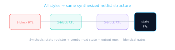
Mealy outputs in 2-block: If outputs depend on inputs, register them explicitly or accept combo timing paths. Production teams often add a 4th "output register" block for Mealy signals that must be glitch-free.
Lint rules your team will enforce
| Rule | Why |
|---|---|
| One sequential block per register group | Prevents multi-driver and mixed blocking/nonblocking |
default in every case (state) | Illegal state recovery — ties to Lesson 6.4 |
next = state before case | Explicit hold default; linter-friendly |
| No outputs assigned in both seq and combo blocks | Multi-driver lint error |
| State diagram checked against case items | 1:1 mapping — missing transition = bug |
Registered latch fix — production 2-block
// 2-block with registered data path (production pattern)
always @(posedge clk or negedge rst_n) begin
  if (!rst_n) begin
    state    <= IDLE;
    data_reg <= 8'h00;
  end else begin
    state <= next;
    if (next == CAP && state == IDLE)
      data_reg <= rx_data;
  end
end

always @(*) begin
  next = state;
  case (state)
    IDLE: if (rx_valid) next = CAP;
    CAP:  next = HOLD;
    HOLD: if (cpu_ack) next = IDLE;
    default: next = IDLE;
  endcase
end

assign byte_ready  = (state == HOLD);
assign stored_byte = data_reg;
Style selection checklist
- Team uses one style consistently — document it in the coding guide
- 2-block minimum for any FSM with >2 states
- 3-block when Moore outputs are numerous or reviewed separately
- Never mix styles within the same module hierarchy level
- Next-state block: default
next = statefirst, full case withdefault - All registers (state + data) live in the sequential block only
- Draw state diagram → map 1:1 to case items in next-state block
🎯 What to remember
- 1-block: fine for learning, avoid in production FSMs.
- 2-block: industry default — seq state + combo next-state.
- 3-block: add dedicated output decode for Moore machines.
- Hardware is the same; pick the style your team can review fastest.