Mux, demux, decoder & priority encoder
Before you build an ALU or a bus arbiter, you need the routing primitives that every datapath reuses: multiplexers pick one of many inputs, demultiplexers fan one input to many outputs, decoders turn an address into one-hot selects, and priority encoders collapse many request lines into a compact index. These blocks are small in code but huge in silicon — understanding gate cost here pays off in every review.
A mux is a controlled switch. A decoder is an address-to-one-hot translator. A priority encoder is the inverse with ranked winners. Synthesis maps all three to AND/OR networks — your RTL style determines how clean that network is.
Why these four blocks show up everywhere
In a CPU, register file read ports are muxes. Instruction decode is a decoder. Interrupt controllers use priority encoders. Chip-select logic on a shared bus is demux + decoder territory. Master these four and you can read almost any combinational datapath schematic.
| Block | Inputs → Output | Typical use |
|---|---|---|
| 2:1 / N:1 mux | N data inputs + select → 1 output | Operand pick, bypass, config |
| 1:N demux | 1 data input + select → N outputs (one active) | Bus fan-out, write strobes |
| Binary decoder | Address + enable → one-hot | Memory chip-select, opcode decode |
| Priority encoder | Request vector → index + valid | Interrupts, arbiters, FIFO empty |
A mux is a TV remote input selector — one screen, many sources. A decoder is a hotel room number that lights exactly one "occupied" LED on the front desk panel. A priority encoder is the front desk reading which highest-numbered floor still has a lit LED.
2:1 multiplexer — truth table & assign style
The simplest mux chooses between two inputs using one select bit. When sel=0, output follows a; when sel=1, output follows b.
| sel | y | Gate intuition |
|---|---|---|
| 0 | a | AND path: a & ~sel |
| 1 | b | AND path: b & sel |
Boolean form: y = (~sel & a) | (sel & b). That's two AND gates, one inverter, one OR — about four gate delays if built from NAND/NOR only.
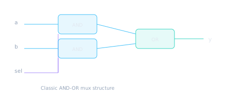
A 2:1 mux is rarely drawn as a triangle in gate-level schematics — it's AND-OR logic.
module mux2 (
  input  wire       a,
  input  wire       b,
  input  wire       sel,
  output wire       y
);
  // Continuous assign — synthesizes to mux cell or AND-OR
  assign y = sel ? b : a;
endmodule
module mux2_always (
  input  wire       a, b, sel,
  output reg        y
);
  always @(*) begin
  y = a;              // default prevents latch
  if (sel) y = b;
  end
endmodule
Writing if (sel) y = b; without a default y = a; (or full else) infers a latch. Muxes are combinational — every input combination must define y.
4:1 multiplexer — case style & gate scaling
A 4:1 mux needs two select bits. For width W, you replicate the mux tree W times — bit-sliced, not byte-wide magic.
| sel | y |
|---|---|
2'b00 | d0 |
2'b01 | d1 |
2'b10 | d2 |
2'b11 | d3 |
Gate-cost intuition: A tree of 2:1 muxes uses three 2:1 muxes per bit (log₂4 = 2 levels). A flat AND-OR implementation grows roughly as 2^S AND terms for S select bits. Synthesis usually picks a mux tree or dedicated mux cells — but wide muxes on FPGAs can dominate routing.
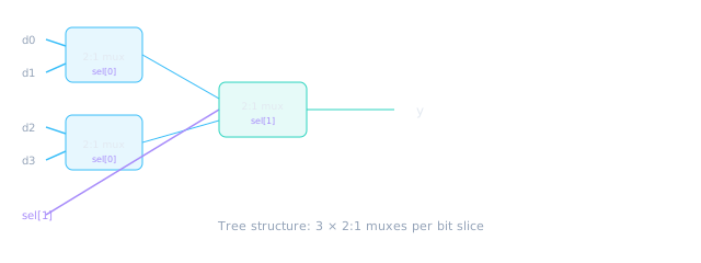
Mux trees scale as O(W × log₂N) for N inputs, width W.
module mux4 #(
  parameter WIDTH = 8
) (
  input  wire [WIDTH-1:0] d0, d1, d2, d3,
  input  wire [1:0]       sel,
  output reg  [WIDTH-1:0] y
);
  always @(*) begin
    case (sel)
      2'b00:   y = d0;
      2'b01:   y = d1;
      2'b10:   y = d2;
      default: y = d3;   // full case — 2'b11
    endcase
  end
endmodule
On ASIC, dedicated mux2/mux4 library cells are fast and area-efficient. On FPGA, wide muxes often map to LUTs — a 32:1 mux on 32-bit data is not "free" like a C switch statement.
Demultiplexer — one input, many outputs
A demux routes a single data input to exactly one of N outputs based on select. The other outputs are typically driven to zero (or left unused with explicit tie-off in lint-clean designs).
| sel | y0 | y1 | y2 | y3 |
|---|---|---|---|---|
| 00 | d | 0 | 0 | 0 |
| 01 | 0 | d | 0 | 0 |
| 10 | 0 | 0 | d | 0 |
| 11 | 0 | 0 | 0 | d |
Structurally, a demux is a decoder on the select lines ANDed with the data input: yi = d & (sel == i).
module demux4 #(
  parameter WIDTH = 8
) (
  input  wire [WIDTH-1:0] d,
  input  wire [1:0]       sel,
  output reg  [WIDTH-1:0] y0, y1, y2, y3
);
  always @(*) begin
    y0 = {WIDTH{1'b0}};
    y1 = {WIDTH{1'b0}};
    y2 = {WIDTH{1'b0}};
    y3 = {WIDTH{1'b0}};
    case (sel)
      2'b00: y0 = d;
      2'b01: y1 = d;
      2'b10: y2 = d;
      default: y3 = d;
    endcase
  end
endmodule
A demux is a postal sorting machine — one letter stream enters, and the bin number (select) decides which output tray gets the letter. Only one tray is active per cycle.
Binary decoder — address to one-hot
A N-bit binary decoder produces 2^N outputs, exactly one high when enabled. This is how a 3-bit address generates eight chip-select lines for a register bank.
| addr | y (one-hot, en=1) |
|---|---|
3'b000 | 8'b00000001 |
3'b001 | 8'b00000010 |
3'b010 | 8'b00000100 |
| … | … |
3'b111 | 8'b10000000 |
| any (en=0) | 8'b00000000 |
Gate-cost warning: A full binary decoder grows exponentially — a 10-bit decoder is 1024 outputs. In practice, designers use partial decode, hierarchical decode, or address comparators for wide spaces.
module decoder3 (
  input  wire       en,
  input  wire [2:0] addr,
  output reg  [7:0] y
);
  always @(*) begin
    y = 8'b0;
    if (en) begin
      case (addr)
        3'b000: y = 8'b00000001;
        3'b001: y = 8'b00000010;
        3'b010: y = 8'b00000100;
        3'b011: y = 8'b00001000;
        3'b100: y = 8'b00010000;
        3'b101: y = 8'b00100000;
        3'b110: y = 8'b01000000;
        default: y = 8'b10000000;
      endcase
    end
  end
endmodule
Using y[i] = (addr == i) & en in a generate loop is fine — but forgetting en means outputs glitch when address changes. Add en in the same expression or default y=0 when disabled.
Priority encoder — highest set bit wins
Unlike a plain encoder (which assumes exactly one input is high), a priority encoder finds the index of the highest-priority active request. Essential for interrupt vectors and bus grant logic.
| req[3:0] | idx | valid | Rule |
|---|---|---|---|
0000 | 00 | 0 | No requests |
0001 | 00 | 1 | Bit 0 wins |
0010 | 01 | 1 | Bit 1 wins |
1011 | 11 | 1 | Bit 3 wins (highest) |
Priority encoding is naturally expressed with if chains from MSB to LSB — synthesis builds a priority tree. Alternatively, use a casez/casex with care (document don't-care assumptions).
module priority_enc4 (
  input  wire [3:0] req,
  output reg  [1:0] idx,
  output reg        valid
);
  always @(*) begin
    idx   = 2'b00;
    valid = 1'b0;
    if (req[3]) begin idx = 2'b11; valid = 1'b1; end
    else if (req[2]) begin idx = 2'b10; valid = 1'b1; end
    else if (req[1]) begin idx = 2'b01; valid = 1'b1; end
    else if (req[0]) begin idx = 2'b00; valid = 1'b1; end
  end
endmodule
Plain encoder
Assumes exactly one input high. Violations produce garbage or X in simulation.
Priority encoder
Handles multiple requests — returns highest index. Safer for real interrupt buses.
Gate-cost cheat sheet
| Block | Outputs | Rough growth | Watch for |
|---|---|---|---|
| 2:1 mux (W bits) | 1 × W | O(W) | Trivial |
| N:1 mux | 1 × W | O(W · log₂N) | Wide N on FPGA routing |
| N-bit decoder | 2^N | Exponential | Don't decode 16-bit addresses fully |
| Priority enc (N req) | log₂N + valid | O(N) priority chain | Long chains → timing |
Review tip: When a senior asks "how big is this mux?", answer in select width and data width. "32:1 on 64 bits" is a very different floorplan than "4:1 on 4 bits."
RTL checklist for routing blocks
- Every combinational block has default assignments before case/if chains
- Full
caseon select — no inferred latches - Decoder
engate forces all outputs low when disabled - Priority encoder outputs explicit
validwhen req = 0 - Parameterize
WIDTH— don't hard-code 8-bit everywhere - Name select vs address consistently in the module header comment
🎯 What to remember
- Mux = pick one of N; demux = fan one to N; decoder = binary to one-hot.
- Priority encoder = ranked collapse of many request bits to an index.
- Gate cost scales with select width and data width — muxes are cheap per bit but wide ones hurt routing.
- Decoders explode exponentially — use hierarchy for wide address spaces.
- Default assignments + full case are non-negotiable for clean synthesis.