2-flop, pulse sync & handshake — when to use which
Three synchronizer families cover most CDC boundaries. Pick by signal type: stable level → 2-flop; single-cycle event → pulse sync; multi-bit payload → req/ack handshake (or FIFO for streaming).
Hardware that safely samples an async signal into a receiving clock domain — trading latency for metastability immunity.
Decision table — match structure to signal
| Signal type | Structure | Latency | Don't use when… |
|---|---|---|---|
| 1-bit level (status, flag) | 2-flop sync | 2+ cycles | Source toggles faster than 2× dest period |
| 1-cycle pulse (event, irq) | Pulse synchronizer | 3–5 cycles | Pulses arrive closer than sync latency |
| Multi-bit data (non-counting) | Req/ack handshake | Variable | High throughput streaming (use FIFO) |
| Counter / pointer | Gray-code 2FF | 2+ cycles | Non-gray binary (bits skew) |
| Streaming bus | Async FIFO | FWFT / skid | Single register write (overkill) |
Gray-code counters, async FIFOs, and CDC anti-patterns are covered in the full CDC course and upcoming lesson 9.7. This lesson focuses on the three structures every designer must write from memory.
2-flop synchronizer — stable 1-bit levels
Use when the source signal stays stable for at least two destination clock cycles. The classic pattern for reset flags, mode bits, and slow status lines.
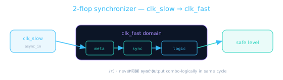
// 2-flop synchronizer — 1-bit level crossing
module sync_2ff (
  input  wire clk_dst,
  input  wire rst_n,
  input  wire async_in,    // from source domain — treat as async
  output wire sync_out
);
  (* ASYNC_REG = "TRUE" *) reg meta, sync;

  assign sync_out = sync;

  always @(posedge clk_dst or negedge rst_n) begin
    if (!rst_n) begin meta <= 1'b0; sync <= 1'b0; end
    else        begin meta <= async_in; sync <= meta; end
  end
endmodule

// Usage: only sample sync_out on posedge clk_dst, never combo-gate it
2-flop on a pulse shorter than the destination period — the pulse may fall between samples and never be seen. Use pulse sync instead.
Pulse synchronizer — single-cycle events
Converts a one-cycle pulse in the source domain into a one-cycle pulse in the destination domain. Common for interrupts and "data ready" strobes.
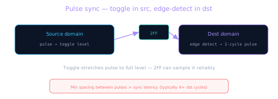
// Pulse synchronizer — toggle-ack scheme (simplified)
module pulse_sync (
  input  wire clk_src, clk_dst,
  input  wire rst_n,
  input  wire pulse_in,      // 1-cycle in src domain
  output wire pulse_out      // 1-cycle in dst domain
);
  reg toggle_src;
  reg sync_a, sync_b, sync_c;

  // Source: flip toggle on each pulse
  always @(posedge clk_src or negedge rst_n) begin
    if (!rst_n) toggle_src <= 1'b0;
    else if (pulse_in) toggle_src <= ~toggle_src;
  end

  // Dest: 3-flop sync + edge detect
  always @(posedge clk_dst or negedge rst_n) begin
    if (!rst_n) {sync_a, sync_b, sync_c} <= 3'b000;
    else        {sync_a, sync_b, sync_c} <= {toggle_src, sync_a, sync_b};
  end
  assign pulse_out = sync_b ^ sync_c;  // edge → pulse
endmodule
Req/ack handshake — multi-bit payload
When you need to move a multi-bit value (not a gray counter), hold data stable and use a handshake: source asserts req, destination acknowledges ack after sampling. Both sides need synchronizers on the control signals.
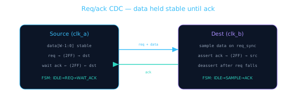
// Source side — hold data, pulse req, wait for ack_sync
typedef enum logic [1:0] {IDLE, SEND_REQ, WAIT_ACK} src_state_t;
src_state_t state;
reg req;
wire ack_sync;  // ack from dst through 2FF into clk_a

always @(posedge clk_a or negedge rst_n) begin
  if (!rst_n) begin state <= IDLE; req <= 0; end
  else case (state)
    IDLE:      if (payload_valid) begin data_hold <= payload; req <= 1; state <= SEND_REQ; end
    SEND_REQ:  state <= WAIT_ACK;
    WAIT_ACK:  if (ack_sync) begin req <= 0; state <= IDLE; done <= 1; end
  endcase
end
// Dest side — detect req_sync rising edge, latch data, return ack
wire req_sync;  // req from src through 2FF into clk_b
reg req_prev, ack;

always @(posedge clk_b or negedge rst_n) begin
  if (!rst_n) begin req_prev <= 0; ack <= 0; end
  else begin
    req_prev <= req_sync;
    if (req_sync && !req_prev) begin   // rising edge
      captured_data <= data_bus;        // data stable during req
      ack <= 1;
    end else if (!req_sync && ack)
      ack <= 0;                          // drop ack after src drops req
  end
end
Never 2FF each bit of a multi-bit bus independently — bits arrive in different cycles. Handshake (or gray/FIFO) keeps the bus coherent.
Quick reference checklist
- Stable 1-bit level → 2-flop sync in destination domain
- 1-cycle pulse → toggle + edge detect (pulse sync)
- Multi-bit register write → req/ack handshake
- Streaming / high throughput → async FIFO (see Async FIFO Overview)
- Counter crossing → gray code + 2FF (lesson 9.7 preview)
- Mark sync flops
ASYNC_REG; constrain as false paths in SDC - Run CDC lint on every block boundary before integration
Latency and throughput trade-offs
| Structure | Typical latency | Max throughput | Area cost |
|---|---|---|---|
| 2-flop sync | 2–3 dst cycles | 1 toggle per 2×Tdst | 2 flops |
| Pulse sync | 4–6 dst cycles | 1 pulse per 4×Tdst min | 3–4 flops + edge logic |
| Req/ack handshake | 6–12 cycles round-trip | ~1 transfer per handshake | FSM both sides + 4+ sync FFs |
| Async FIFO | 2–4 cycles (FWFT) | 1 word/cycle steady state | RAM + gray pointers + sync |
Choose the cheapest structure that meets throughput. A status flag polled every millisecond does not need a 512-deep FIFO. A PCIe completion queue does.
// Latency budget example: IRQ from slow peripheral to CPU
// clk_periph = 50 MHz (20 ns), clk_cpu = 1 GHz (1 ns)
// 2-flop sync: 2–3 cpu cycles ≈ 2–3 ns — acceptable for IRQ
// Pulse sync:  4–6 cpu cycles ≈ 4–6 ns — use if source sends 1-cycle pulse
// Handshake:   10+ cycles — overkill for single IRQ bit

// Rule: measure end-to-end latency in destination cycles,
//       compare to protocol spec, then pick structure
Go deeper
Module 9.7 covers CDC anti-patterns (bus bit-sync, XOR sync) and gray-code pointers. For MTBF calculations, formal CDC, and production FIFO templates, continue to the CDC deep-dive course.
🎯 What to remember
- 2-flop: stable levels. Pulse sync: events. Handshake: multi-bit payloads.
- Never bit-sync a bus — coherence requires handshake, gray, or FIFO.
- Control signals cross with 2FF; data stays stable until ack.
- Match structure to signal type — wrong sync = silent silicon bug.
- Next: CDC don'ts — bus bit-sync, gray pointers, and what not to do.