Reset — why chips need a clean start
At power-on, flip-flop values are unknown (X) in simulation and random in silicon. Reset forces a known starting state so FSMs, counters, and control bits begin safely.
Without reset, two chips of the same design can boot into different illegal FSM states — and never recover.
What reset must initialize
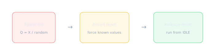
Reset path: unknown → known → functional operation.
- FSM state registers → IDLE
- Counters / pointers → 0
- Control strobes (start, we, irq) → inactive
- Status sticky bits → clear (or documented power-on value)
Datapath RAM contents — block RAMs and large memories often power up unknown and are not cleared on reset (too slow, too costly). Software initializes them, or you accept garbage until first write. Configuration registers loaded from EEPROM may keep values across soft reset. Only reset control state that must be deterministic at boot.
| Signal class | Reset? | Why |
|---|---|---|
| FSM state, counters | Yes | Must start from known IDLE/0 |
| Output enables, irq pending | Yes | Prevent spurious activity |
| Large SRAM array | Often no | Reset all entries = many cycles / huge area |
| Pipeline data flops | Sometimes | Flush with valid=0; data may be don't-care |
Active-high vs active-low — naming matters
Reset polarity is encoded in the signal name. Industry convention: suffix _n or _b means active-low (asserted when logic 0). No suffix often means active-high (asserted when logic 1). Always read the port list — do not assume.
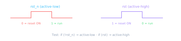
The waveform shape is inverted — the name tells you which level means “in reset.”
| Name pattern | Asserted when | Typical check in always |
|---|---|---|
rst_n, reset_n, aresetn | Logic 0 | if (!rst_n) q <= 0; |
rst, reset, srst | Logic 1 | if (rst) q <= 0; |
por_n | Power-on reset, active-low | Chip-level, before clocks stable |
Inverting reset in one module but not updating the testbench — rst_n=1 held forever while RTL waits for !rst_n → design never leaves reset. Match polarity end-to-end.
Async vs sync reset — syntax and meaning
| Style | Sensitivity | Pros | Cons |
|---|---|---|---|
| Async assert | posedge clk or negedge rst_n | Resets even if clock is dead | Release must be sync’d (glitch/CDC) |
| Sync reset | posedge clk only; check rst inside | Cleaner timing, easier STA | Needs toggling clock to take effect |
// Active-low async reset (very common ASIC/FPGA style)
module reset_async (
  input  wire clk,
  input  wire rst_n,   // 0 = reset
  input  wire d,
  output reg  q
);
  always @(posedge clk or negedge rst_n) begin
    if (!rst_n)
      q <= 1'b0;       // async assert path
    else
      q <= d;
  end
endmodule
// Fully synchronous reset (active-high here)
module reset_sync (
  input  wire clk,
  input  wire rst,     // 1 = reset
  input  wire d,
  output reg  q
);
  always @(posedge clk) begin
    if (rst)
      q <= 1'b0;
    else
      q <= d;
  end
endmodule
Industry habit: Many teams use async assert, sync deassert — reset can slam flops immediately, but release is synchronized so all flops leave reset on the same clock edge.
// Reset control flops; leave RAM datapath uninitialized
module reset_selective (
  input  wire        clk,
  input  wire        rst_n,
  input  wire [7:0]  wr_data,
  input  wire        wr_en,
  output reg  [1:0]  state,      // MUST reset
  output reg  [7:0]  ram [0:15]  // typically NO hardware reset
);
  integer i;
  always @(posedge clk or negedge rst_n) begin
    if (!rst_n) begin
      state <= 2'd0;               // FSM → IDLE
      // Do NOT loop-clear ram[] — software writes first
    end else begin
      if (wr_en) ram[state] <= wr_data;
      // state transitions...
    end
  end
endmodule
Reset synchronizer (preview)
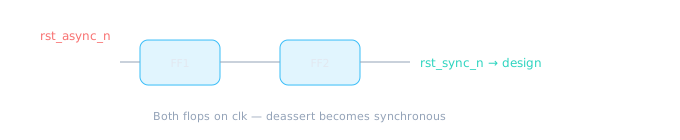
You will code this properly in Module 5; know the diagram now.
// Skeleton — async assert, sync deassert of active-low reset
module reset_syncer (
  input  wire clk,
  input  wire rst_async_n,
  output reg  rst_sync_n
);
  reg meta;
  always @(posedge clk or negedge rst_async_n) begin
    if (!rst_async_n) begin
      meta       <= 1'b0;
      rst_sync_n <= 1'b0;
    end else begin
      meta       <= 1'b1;
      rst_sync_n <= meta;
    end
  end
endmodule
Testbench reset sequence
module tb_reset_sequence;
  reg clk = 0, rst_n = 0;
  always #5 clk = ~clk;

  initial begin
    rst_n = 0;          // assert reset
    repeat (3) @(posedge clk);
    rst_n = 1;          // deassert after a few clocks
    repeat (10) @(posedge clk);
    $finish;
  end
endmodule
Trap: Releasing reset in simulation at time 0 with no clocks often hides bugs. Hold reset for several cycles, then release.
🎯 What to remember
- Reset creates a known boot state — mandatory for control flops.
- Know async vs sync syntax and when each is used.
- Deassert carefully (synchronizer) in multi-clock chips.
- Know active-low (
rst_n) vs active-high (rst) naming. - Don't assume RAM arrays reset — reset control, initialize data in SW.
- Next: timing diagram literacy — reading waveforms.