Lab: parameterized counter + clean reset strategy
Module 5 capstone. You build a parameterized modulo counter with
WIDTH, MAX, load, and enable — wired through a
reset synchronizer for async-assert / sync-deassert discipline.
Paste the DUT and self-checking testbench into the simulator and confirm every mode works.
Produce param_counter plus param_counter_tb — synthesizable, lint-clean, and covering reset, load, enable-hold, count-to-MAX wrap, and synchronizer latency.
Block diagram — what you're building
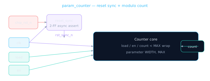
Chip reset enters synchronizer; counter logic only sees rst_sync_n.
| Port | Direction | Description |
|---|---|---|
clk | Input | Counter clock |
chip_rst_n | Input | Chip-wide async reset (active-low) |
load | Input | Load load_val into counter (priority over en) |
load_val[WIDTH-1:0] | Input | Parallel load value |
en | Input | Increment when high (and not loading) |
count[WIDTH-1:0] | Output | Current count, wraps at MAX-1 → 0 |
This lab is a programmable lap counter at a track: reset clears everyone to the start line (via the synchronizer's "official go" signal), load sets a specific lap number, and enable counts laps until MAX then wraps.
Step 1 — Reset synchronizer (inline)
  reg sync_ff1, sync_ff2;
  wire rst_sync_n;

  always @(posedge clk or negedge chip_rst_n) begin
    if (!chip_rst_n) begin
      sync_ff1 <= 1'b0;
      sync_ff2 <= 1'b0;
    end else begin
      sync_ff1 <= 1'b1;
      sync_ff2 <= sync_ff1;
    end
  end
  assign rst_sync_n = sync_ff2;
Step 2 — Counter next-state logic
  localparam [WIDTH-1:0] LAST = MAX - 1;

  always @(posedge clk or negedge rst_sync_n) begin
    if (!rst_sync_n)
      count <= {WIDTH{1'b0}};
    else if (load)
      count <= load_val;
    else if (en) begin
      if (count == LAST)
        count <= {WIDTH{1'b0}};
      else
        count <= count + 1'b1;
    end
  end
Counter FFs use rst_sync_n (synchronized), not raw chip_rst_n. The synchronizer FFs themselves use chip_rst_n for async assert.
Full DUT — paste-ready module
// param_counter — Module 5.7 lab DUT
// Parameterized modulo counter + inline reset synchronizer
module param_counter #(
  parameter WIDTH = 8,
  parameter MAX   = 10   // counts 0 .. MAX-1
) (
  input  wire             clk,
  input  wire             chip_rst_n,
  input  wire             load,
  input  wire [WIDTH-1:0] load_val,
  input  wire             en,
  output reg  [WIDTH-1:0] count
);
  localparam [WIDTH-1:0] LAST = MAX - 1;

  // --- Reset synchronizer (async assert, sync deassert) ---
  reg sync_ff1, sync_ff2;
  wire rst_sync_n;

  always @(posedge clk or negedge chip_rst_n) begin
    if (!chip_rst_n) begin
      sync_ff1 <= 1'b0;
      sync_ff2 <= 1'b0;
    end else begin
      sync_ff1 <= 1'b1;
      sync_ff2 <= sync_ff1;
    end
  end
  assign rst_sync_n = sync_ff2;

  // --- Counter core ---
  always @(posedge clk or negedge rst_sync_n) begin
    if (!rst_sync_n)
      count <= {WIDTH{1'b0}};
    else if (load)
      count <= load_val;
    else if (en) begin
      if (count == LAST)
        count <= {WIDTH{1'b0}};
      else
        count <= count + 1'b1;
    end
  end
endmodule
Self-checking testbench
Tests reset latency, load, enable-hold, count-through-wrap, and post-reset behavior.
// Self-checking testbench for param_counter (MAX=10, WIDTH=8)
module param_counter_tb;
  reg        clk, chip_rst_n, load, en;
  reg  [7:0] load_val;
  wire [7:0] count;

  param_counter #(.WIDTH(8), .MAX(10)) dut (
    .clk(clk), .chip_rst_n(chip_rst_n),
    .load(load), .load_val(load_val), .en(en),
    .count(count)
  );

  initial clk = 0;
  always #5 clk = ~clk;

  integer errors;
  reg [7:0] expect;

  task check;
    input [255:0] name;
    begin
      #1;
      if (count !== expect) begin
        $display("FAIL %s: got %0d expected %0d", name, count, expect);
        errors = errors + 1;
      end else
        $display("PASS %s (count=%0d)", name, count);
    end
  endtask

  initial begin
    errors = 0;
    chip_rst_n = 0; load = 0; en = 0; load_val = 8'd0;

    // Hold reset 3 cycles, release
    repeat(3) @(posedge clk);
    chip_rst_n = 1;
    // Wait 2 sync cycles + 1 for counter reset
    repeat(3) @(posedge clk);
    expect = 0; check("after_reset");

    // Load 7
    load = 1; load_val = 8'd7;
    @(posedge clk); load = 0;
    expect = 7; check("after_load");

    // Enable: 7→8→9→0 (wrap at MAX=10)
    en = 1;
    @(posedge clk); expect = 8; check("inc_to_8");
    @(posedge clk); expect = 9; check("inc_to_9");
    @(posedge clk); expect = 0; check("wrap_to_0");

    // Hold when en=0
    en = 0;
    @(posedge clk); expect = 0; check("hold_at_0");

    // Async reset assert
    chip_rst_n = 0;
    @(posedge clk);
    chip_rst_n = 1;
    repeat(3) @(posedge clk);
    expect = 0; check("after_async_reset");

    if (errors == 0)
      $display("=== ALL TESTS PASSED ===");
    else
      $display("=== %0d TESTS FAILED ===", errors);
    $finish;
  end
endmodule
Extension challenges
Add down-count mode
Input up_down: decrement and wrap MAX-1 when at 0.
Terminal-count flag
Output tc high when count == LAST — useful for FSM triggers.
Gray count output
Add gray_count port using (count>>1)^count from Lesson 5.2.
Your counter's terminal-count flag becomes an FSM input in Module 6 — "when count reaches N, transition to next state." Sequential building blocks feed control logic.
Module 5 checkpoint
Before moving to FSMs, confirm you can do each of these without notes:
- Write a DFF template with enable and async active-low reset
- Implement binary and modulo-N counters with parameterized MAX
- Build SIPO/PISO shift registers and explain bit order
- Design a 1W2R register file with r0=0 convention
- Explain async vs sync reset trade-offs and recovery/removal
- Code a 2-FF reset synchronizer with correct active-low polarity
- Integrate reset sync + parameterized counter with self-checking TB
Module 6 is next: FSMs & Control Logic — Moore vs Mealy, state encoding, and handshakes. Your counter becomes a timer inside a state machine.
🎯 What to remember
- Production counters are parameterized (WIDTH, MAX) with load, en, and clean reset.
- Chip reset → synchronizer → rst_sync_n → your sequential logic.
- Self-checking TB must test reset latency, load priority, wrap, and hold.
- Module 5 complete — you can build registered datapath components from scratch.