Reset synchronizers — async assert, sync deassert
The industry-standard reset strategy combines the best of both worlds: assert reset asynchronously (chip enters safe state immediately) and deassert reset synchronously (no recovery/removal violations). The bridge is a 2-flip-flop reset synchronizer — this lesson shows exactly how it works and how to code it with correct polarity.
Feed the chip-wide async rst_n into a 2-FF synchronizer clocked by each domain's clock. The synchronizer output rst_sync_n is what your RTL logic uses — assert is immediate (async path), deassert is delayed 2 cycles (sync path).
2-FF reset synchronizer — circuit
Two flip-flops in series, both using async reset (so assert is instant) and clocked by the local domain clock. The output is a glitch-free, synchronized reset release.
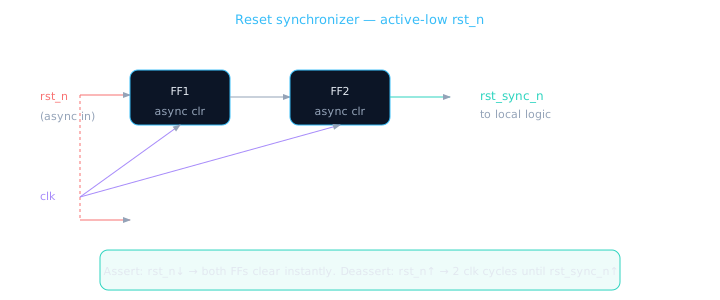
Active-low reset: FFs clear when rst_n=0; rst_sync_n only rises after FF2 sees rst_n=1 for two consecutive clock edges.
| Phase | rst_n (chip) | FF1 / FF2 | rst_sync_n |
|---|---|---|---|
| Reset asserted | 0 | Async clear → 0 | 0 (logic held in reset) |
| Deassert begins | 1 | FF1 samples 1 at clk↑ | Still 0 (FF2 not yet updated) |
| 1 cycle later | 1 | FF2 samples FF1=1 | 1 (logic exits reset cleanly) |
Think of two security guards checking an "all clear" signal. The emergency alarm (async assert) stops everything instantly. But the "resume operations" order must be passed guard-to-guard on schedule (sync deassert) — you can't just shout "go" mid-shift-change.
Correct polarity — active-low rst_n
Most designs use active-low rst_n. The synchronizer FFs are preset to 0 (in reset) and sample rst_n directly — when rst_n=0, async clear forces output low.
module reset_sync (
  input  wire clk,
  input  wire rst_n,       // async chip reset (active-low)
  output wire rst_sync_n   // synchronized reset for this clock domain
);
  reg sync_ff1, sync_ff2;

  // Both FFs: async assert (negedge rst_n), sync deassert
  always @(posedge clk or negedge rst_n) begin
    if (!rst_n) begin
      sync_ff1 <= 1'b0;
      sync_ff2 <= 1'b0;
    end else begin
      sync_ff1 <= 1'b1;
      sync_ff2 <= sync_ff1;
    end
  end

  assign rst_sync_n = sync_ff2;
endmodule
Do NOT invert rst_n before the synchronizer and then invert again after — double inversion hides bugs. Feed rst_n directly to async clear; output is rst_sync_n (also active-low).
Using rst_sync_n in your logic
Instantiate one reset synchronizer per clock domain. All flops in that domain use rst_sync_n, not the raw chip reset.
wire rst_sync_n;
reset_sync u_rst_sync (
  .clk(clk),
  .rst_n(chip_rst_n),
  .rst_sync_n(rst_sync_n)
);

// All logic in this domain uses rst_sync_n
always @(posedge clk or negedge rst_sync_n) begin
  if (!rst_sync_n)
    count <= 8'h00;
  else if (en)
    count <= count + 1'b1;
end
Latency cost: After chip reset deasserts, logic waits 2 clock cycles before operating. This is acceptable — boot sequences account for it. The alternative (async deassert) is STA failure.
Active-high variant
If your project uses active-high rst, the structure is identical but polarity flips. Document which convention your block uses.
// Active-high rst — less common but seen in legacy IP
always @(posedge clk or posedge rst) begin
  if (rst) begin
    sync_ff1 <= 1'b0;
    sync_ff2 <= 1'b0;
  end else begin
    sync_ff1 <= 1'b1;
    sync_ff2 <= sync_ff1;
  end
end
assign rst_sync = sync_ff2;
Reset synchronizer checklist
- One synchronizer instance per clock domain — never share across domains
- Both synchronizer FFs use async assert matching chip reset polarity
- Output
rst_sync_nfeeds all flops in the domain — not rawrst_n - Account for 2-cycle reset latency in boot / init sequences
- Simulation: verify assert is instant, deassert is delayed exactly 2 clocks
- Never put async reset on the synchronizer FFs AND sync reset on downstream — be consistent
🎯 What to remember
- Reset synchronizer = 2 FFs with async assert, sync deassert — the industry default.
- Chip
rst_n→ synchronizer →rst_sync_n→ your logic. - Assert is immediate; deassert takes 2 clock cycles — this is intentional and correct.
- Lesson 5.7 lab ties parameterized counter + this reset strategy together.