Counters — binary, modulo-N & Gray
A counter is a chain of flip-flops with feedback: each clock edge bumps a stored value. Binary counters are the default for timers and addresses. Modulo-N counters wrap at a fixed maximum. Gray counters change one bit at a time — essential when a counter value must cross a clock domain safely.
Counter RTL = registered state + next-state logic. count <= count + 1 is a binary up-counter; compare against MAX-1 for modulo wrap; Gray encoding trades binary arithmetic for single-bit transitions.
Binary up/down counter
The simplest counter increments (or decrements) on every enabled clock edge. Synthesis builds an adder/subtractor feeding a register bank.
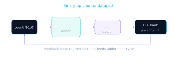
Count register → increment logic → mux (load vs next) → DFFs → back to count.
module bin_counter #(
  parameter WIDTH = 8
) (
  input  wire             clk,
  input  wire             rst_n,
  input  wire             en,
  input  wire             up_down,  // 1=up, 0=down
  output reg  [WIDTH-1:0] count
);
  always @(posedge clk or negedge rst_n) begin
    if (!rst_n)
      count <= {WIDTH{1'b0}};
    else if (en)
      count <= up_down ? (count + 1'b1) : (count - 1'b1);
  end
endmodule
A binary counter is an odometer in base-2: each digit flips when the digit to its right rolls over. At 1111→0000, every bit changes at once — that's the CDC hazard Gray code solves.
Modulo-N counter
Wrap at N instead of 2WIDTH. Common for baud-rate dividers, PWM periods, and round-robin arbiters.
| MAX | Sequence (4-bit) | Use case |
|---|---|---|
| 16 (full) | 0→1→…→15→0 | Free-running address |
| 10 | 0→1→…→9→0 | Decimal timer |
| 5 | 0→1→2→3→4→0 | 5-phase state index |
module modulo_counter #(
  parameter WIDTH = 4,
  parameter MAX   = 10   // counts 0 .. MAX-1
) (
  input  wire             clk,
  input  wire             rst_n,
  input  wire             en,
  output reg  [WIDTH-1:0] count
);
  localparam [WIDTH-1:0] LAST = MAX - 1;

  always @(posedge clk or negedge rst_n) begin
    if (!rst_n)
      count <= {WIDTH{1'b0}};
    else if (en) begin
      if (count == LAST)
        count <= {WIDTH{1'b0}};
      else
        count <= count + 1'b1;
    end
  end
endmodule
If MAX is not a power of 2, ensure WIDTH is wide enough to represent MAX-1. A modulo-10 counter needs at least 4 bits.
Gray code counter — why one bit changes
Adjacent Gray codes differ by exactly one bit. When a pointer crosses clock domains via a 2-FF synchronizer, a binary value sampled mid-transition can be arbitrary garbage; a Gray value is at worst off by one.
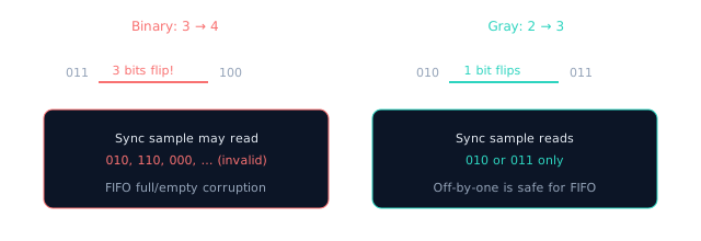
Gray encoding is not magic — it constrains transitions so synchronizers see valid adjacent values.
// Binary counter + Gray output (common FIFO pointer pattern)
module gray_counter #(
  parameter WIDTH = 4
) (
  input  wire             clk,
  input  wire             rst_n,
  input  wire             en,
  output reg  [WIDTH-1:0] bin_count,
  output wire [WIDTH-1:0] gray_count
);
  function [WIDTH-1:0] bin2gray;
    input [WIDTH-1:0] b;
    bin2gray = (b >> 1) ^ b;
  endfunction

  always @(posedge clk or negedge rst_n) begin
    if (!rst_n)
      bin_count <= {WIDTH{1'b0}};
    else if (en)
      bin_count <= bin_count + 1'b1;
  end

  assign gray_count = bin2gray(bin_count);
endmodule
Async FIFOs (Module 7) keep binary pointers internally but export Gray-encoded values across domains. You'll revisit this in the CDC course — for now, know why Gray exists.
Counter comparison table
| Type | Wrap point | Bits toggled/step | Best for |
|---|---|---|---|
| Binary up/down | 2WIDTH | 1 to WIDTH | Addresses, timers in one domain |
| Modulo-N | MAX | 1 to WIDTH | Fixed-period dividers |
| Gray (derived) | 2WIDTH | Exactly 1 | CDC pointers, low-glitch buses |
Counter checklist
- Reset brings count to known value (usually 0)
engates increments — don't burn power counting when idle- Modulo compare uses
MAX-1as last valid value - Gray output derived from binary — don't increment Gray directly unless you know the math
- Document whether count is synchronous to which clock domain
🎯 What to remember
- Counters are registered state + increment/compare logic — the first real sequential building block.
- Modulo-N = compare and wrap; parameterize
MAXfor reuse. - Binary rollovers flip many bits; Gray changes one — critical for CDC pointers.
- Lesson 5.7 lab combines parameterized counter + clean reset into one integrated exercise.