Flip-flops in RTL terms
Module 4 built combinational logic — outputs that change instantly. Module 5 starts with the primitive that
gives hardware memory: the D flip-flop. In RTL you never instantiate
transistor-level gates; you describe behavior with always @(posedge clk) and let synthesis map to
library FFs. This lesson teaches the templates every sequential block inherits.
A D flip-flop samples input D on the active clock edge and holds it on output Q until the next edge. RTL models this with non-blocking assignments inside a clocked always block.
Gate-level FF vs RTL abstraction
At the transistor level, a DFF has D, CLK, optional RESET/SET, Q, and Qn (inverted output). RTL authors work one level up: they declare a reg or logic and describe what happens each clock edge.
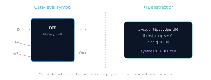
RTL never draws Qn unless you explicitly need an inverted registered signal — synthesis provides it internally.
| Gate-level port | RTL equivalent | Notes |
|---|---|---|
D | Right-hand side of <= | Next-state value sampled at edge |
CLK | posedge clk in sensitivity list | Match your clocking convention (posedge typical) |
RESET | if (!rst_n) or if (rst) | Async: add to sensitivity list; sync: clock-only list |
Q | Registered reg/logic | Drives downstream logic or top-level port |
Qn | Rarely used in RTL | Use ~q combinationally if needed — don't register twice |
A flip-flop is a camera shutter: at each clock tick it takes a snapshot of D and prints it on Q. Between ticks, Q holds the last photo even if D wiggles wildly.
The canonical DFF templates
Four patterns cover 95% of sequential RTL. Memorize these before writing counters or FSMs.
// Basic DFF — no reset (rare in real designs)
always @(posedge clk) begin
  q <= d;
end
// Async reset: rst_n in sensitivity list, tested first
always @(posedge clk or negedge rst_n) begin
  if (!rst_n)
    q <= 1'b0;
  else
    q <= d;
end
// Sync reset: only clock in sensitivity list
always @(posedge clk) begin
  if (!rst_n)
    q <= 1'b0;
  else
    q <= d;
end
Using blocking = inside a clocked always block causes race conditions in simulation and is a lint violation. Always use <= for sequential logic.
Enable — hold vs update
An enabled flip-flop updates Q only when en is high; otherwise it holds. This is how clock-gated datapaths and valid-strobe pipelines are built at the RTL level.
always @(posedge clk or negedge rst_n) begin
  if (!rst_n)
    q <= {WIDTH{1'b0}};
  else if (en)
    q <= d;
  // implicit hold when en=0 — no else needed
end
| Signal | When active | Effect on Q |
|---|---|---|
en = 0 | Between updates | Hold previous value |
en = 1 | At posedge clk | Capture d |
!rst_n (async) | Any time | Force reset value immediately |
(async rst assumed deasserted)
Async vs sync reset ports — preview
Lesson 5.5 goes deep on team policy. For now, know the RTL difference: async reset adds the reset pin to the sensitivity list; sync reset does not. Synthesis must match your library cell's reset style or timing will break.
Industry default: Many SoCs use async assert, sync deassert via a reset synchronizer (Lesson 5.6). Your FF template still uses posedge clk or negedge rst_n when the library FF has async clear.
Complete parameterized DFF module
Wrap the template in a reusable module — the same pattern you'll use for register files and pipeline stages.
module dff #(
  parameter WIDTH = 8
) (
  input  wire             clk,
  input  wire             rst_n,
  input  wire             en,
  input  wire [WIDTH-1:0] d,
  output reg  [WIDTH-1:0] q
);
  always @(posedge clk or negedge rst_n) begin
    if (!rst_n)
      q <= {WIDTH{1'b0}};
    else if (en)
      q <= d;
  end
endmodule
Flip-flop coding checklist
- Clocked blocks use
always @(posedge clk)— one clock domain per block - Non-blocking
<=for all registered assignments - Reset tested first inside the block; polarity matches port name (
rst_n→if (!rst_n)) - Async reset appears in sensitivity list; sync reset does not
- Enable uses
else if (en)— implicit hold, no redundantelse q <= q - Do not mix
assignandalwayson the sameqsignal
🎯 What to remember
- RTL flip-flops =
always @(posedge clk)+<=— synthesis maps to library DFF cells. - Work with
Q;Qnis a gate-level detail unless you explicitly need inverted registered outputs. - Enable means "update this cycle"; no enable means "update every cycle".
- Async vs sync reset differs only in the sensitivity list — but has huge timing/DFT implications (Lessons 5.5–5.6).