Datapath + control co-design
A processor is not "an FSM plus some logic." It's a datapath (registers, ALU, muxes, memories) steered by a control FSM that asserts the right enables and selects each cycle. Co-design means drawing both together — every state maps to concrete hardware action.
Datapath = the data-processing hardware (regfile, ALU, shifters, buses). Control = FSM or microcoded sequencer that drives reg_we, alu_op, mux_sel, and mem_en. They are designed as one unit.
The split — what control drives
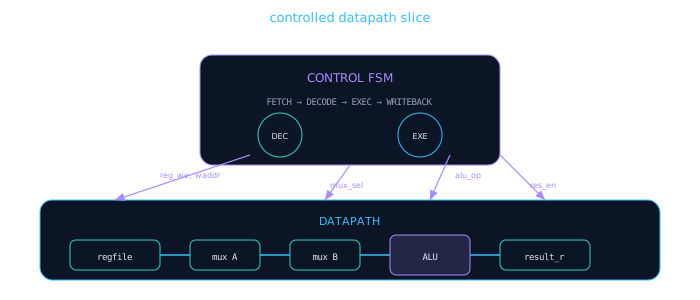
Control sits above the datapath, broadcasting enables and mux selects. Data flows left-to-right through registers and combinational logic.
| Control signal | Datapath target | When asserted |
|---|---|---|
reg_we | Register file write port | WRITEBACK state, valid dest |
waddr[1:0] | Regfile write address | DECODE latches dest field |
alu_op[2:0] | ALU function select | EXEC state |
mux_a_sel | ALU input A mux | EXEC — reg vs immediate |
res_en | Result register load | EXEC end — capture ALU out |
The datapath is a kitchen: ingredients on counters (registers), knives and stoves (ALU), and pipes between stations (buses). The control FSM is the head chef calling "chop!", "mix!", "plate!" — each command maps to a specific station and action for exactly one beat.
Register boundaries — where to pipeline
Every register is a timing boundary. Control must know what's registered vs combinational:
- Input registers — stabilize external inputs; control reads stable opcode/operands in DECODE
- Result register — ALU output registered before WRITEBACK; allows multi-cycle EXEC if needed
- Control state register — FSM state is always registered; Moore outputs stable for full cycle
Asserting reg_we in EXEC when the ALU result isn't registered yet writes the previous cycle's result. Match control state to the pipeline stage where data is actually valid.
Micro-operation table (control plan)
Before writing RTL, fill a table mapping each FSM state to control signals. This is the co-design artifact reviewers want to see.
| State | reg_we | alu_op | mux_a_sel | mux_b_sel | res_en | Next |
|---|---|---|---|---|---|---|
IDLE | 0 | — | — | — | 0 | start → FETCH |
FETCH | 0 | — | — | — | 0 | instr_rdy → DECODE |
DECODE | 0 | — | — | — | 0 | → EXEC |
EXEC | 0 | from opcode | reg/imm | reg/imm | 1 | → WRITEBACK |
WRITEBACK | 1 | — | — | — | 0 | → IDLE |
Example — controlled ALU/regfile slice
// Controlled datapath slice: 4-reg regfile + muxed ALU
// Control FSM drives enables; datapath is purely structural
module ctrl_datapath_slice (
  input  wire       clk,
  input  wire       rst_n,
  input  wire       start,
  input  wire [7:0] instr,       // [7:6]=opcode [5:4]=rs [3:2]=rt [1:0]=rd
  output wire       done
);
  localparam IDLE=0, FETCH=1, DECODE=2, EXEC=3, WB=4;
  reg [2:0] state, next;
  reg [7:0] instr_r;
  reg [7:0] regs [0:3];
  reg [7:0] result_r;

  wire [1:0] rs = instr_r[5:4];
  wire [1:0] rt = instr_r[3:2];
  wire [1:0] rd = instr_r[1:0];
  wire [1:0] op = instr_r[7:6];

  wire [7:0] op_a = regs[rs];
  wire [7:0] op_b = regs[rt];
  wire [7:0] alu_out = (op == 2'b00) ? op_a + op_b :
                       (op == 2'b01) ? op_a - op_b :
                       (op == 2'b10) ? op_a & op_b :
                                        op_a ^ op_b;

  // Control outputs (Moore from state)
  wire reg_we  = (state == WB);
  wire res_en  = (state == EXEC);
  assign done  = (state == WB);

  // Datapath registers
  always @(posedge clk or negedge rst_n) begin
    if (!rst_n) begin
      instr_r  <= 8'h00;
      result_r <= 8'h00;
      regs[0]  <= 8'h00;
      regs[1]  <= 8'h00;
      regs[2]  <= 8'h00;
      regs[3]  <= 8'h00;
    end else begin
      if (state == FETCH)  instr_r  <= instr;
      if (res_en)          result_r <= alu_out;
      if (reg_we)          regs[rd]  <= result_r;
    end
  end

  // FSM (3-block style)
  always @(posedge clk or negedge rst_n)
    if (!rst_n) state <= IDLE; else state <= next;

  always @(*) begin
    next = IDLE;
    case (state)
      IDLE:   if (start)     next = FETCH;
      FETCH:  next = DECODE;
      DECODE: next = EXEC;
      EXEC:   next = WB;
      WB:     next = IDLE;
      default: next = IDLE;
    endcase
  end
endmodule
Co-design check: In EXEC, res_en=1 captures ALU output into result_r. In WB, reg_we=1 writes result_r to regs[rd]. The ALU is combinational — never write regfile directly from alu_out in EXEC.
Control decode block
// Separate control decode — maps state + opcode → datapath signals
// Cleaner when datapath grows beyond one ALU
always @(*) begin
  reg_we  = 1'b0;
  res_en  = 1'b0;
  alu_op  = 3'b000;
  mux_a_sel = 1'b0;
  case (state)
    EXEC: begin
      res_en = 1'b1;
      case (opcode)
        OP_ADD: alu_op = 3'b000;
        OP_SUB: alu_op = 3'b001;
        OP_AND: alu_op = 3'b010;
        OP_XOR: alu_op = 3'b011;
        default: alu_op = 3'b111; // safe NOP
      endcase
    end
    WB: reg_we = 1'b1;
    default: ;
  endcase
end
"How do you verify control/datapath co-design?" — Build a micro-op table, write directed tests per state, and assert that no control signal is X in any reachable state. Scoreboarding compares architectural state (regfile) against a C model.
Timing — one micro-op per cycle or multi-cycle?
Your FSM states must match your pipeline depth. A 5-stage RISC pipeline has 5 states (or one hot state per stage). A multi-cycle microcoded machine may revisit EXEC several times for multiply.
Hazard preview — why control gets hard
When you pipeline this slice in Module 8, control must handle hazards — situations where the datapath would read stale data:
| Hazard type | Example | Control fix |
|---|---|---|
| Structural | Single ALU, two ops same cycle | Serialize in FSM states |
| Data (RAW) | ADD r1,r2,r3 then SUB r3,r1,r2 back-to-back | Stall or forward from EXE/MEM |
| Control | Branch changes PC while fetch in flight | Flush fetch/decode registers |
Adding pipeline registers without updating the FSM is the #1 datapath/control bug. Every new register adds one cycle of latency — the micro-op table must stretch to match.
Module 8 preview: You'll retime this same ALU/regfile slice into a 2- or 3-stage pipeline and add forwarding muxes. The micro-op table becomes a pipeline schedule.
Co-design checklist
- Draw datapath diagram and control FSM before coding either
- Fill micro-op table: every state → all control signals (no X's)
- Place registers at stage boundaries; document latency per operation
- Moore control outputs stable for full cycle — no combo from datapath feedback
- Verify regfile write uses registered result, not combo ALU output
- Safe default: all enables low in
defaultFSM branch
🎯 What to remember
- Control FSM generates enables and mux selects; datapath executes the operations.
- Co-design = micro-op table + block diagram before RTL — not FSM first, datapath later.
- Register boundaries define when data is valid; control states must align.
- Next lesson: put it all together in the Module 7 mini-project lab.