Module, ports & hierarchy — your first file
Every Verilog design is a tree of modules. A module is a reusable block with a port list (the boundary pins) and an internal body. Today you write your first complete DUT + testbench and learn how parent modules wire children together.
A module is the fundamental building block of RTL — like a function with hardware pins. module ... endmodule wraps everything.
The module skeleton
Every synthesizable file starts with a module declaration. The name becomes the cell type in the netlist. Ports are the only signals that cross the boundary.
module my_block (
  input  wire       clk,
  input  wire       rst_n,
  input  wire [7:0] data_in,
  output wire [7:0] data_out
);
  // internal logic lives here
endmodule
| Keyword | Role | Notes |
|---|---|---|
module | Opens a design unit | Name must be unique in the project (usually) |
endmodule | Closes the unit | Required — missing it is a syntax error |
input | Signal driven from outside | Cannot be assigned inside the module |
output | Signal driven from inside | Needs a driver: assign or always |
inout | Bidirectional pin | Tristate buses — advanced; avoid early |
Think of a module as a chip package: the ports are the pins on the package, and the body is the silicon inside. Parent modules solder wires between child packages.
Port directions — who drives what
Direction tells the compiler who is allowed to assign each net. Violating this causes elaboration errors or simulation X-propagation.
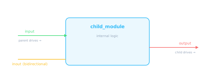
Input = driven from outside. Output = driven from inside. Inout = shared bus with tristate control.
| Direction | Driver | Typical use | Beginner? |
|---|---|---|---|
input | Parent / TB | Clocks, data, control | ✓ daily |
output | This module | Results, status flags | ✓ daily |
inout | Either side (tristate) | I²C, shared memory bus | Later |
Assigning to an input port inside the module is illegal. If you need to modify an input, copy it to an internal wire first.
ANSI vs non-ANSI port style
Verilog-2001 introduced ANSI ports — direction and type in the port list. Older style declares ports first, then types separately. Both work; ANSI is standard in modern code.
// --- ANSI style (preferred) ---
module adder_ansi (
  input  wire [3:0] a,
  input  wire [3:0] b,
  output wire [4:0] sum
);
  assign sum = a + b;
endmodule

// --- Non-ANSI style (legacy) ---
module adder_legacy (a, b, sum);
  input  [3:0] a, b;
  output [4:0] sum;
  wire [4:0] sum;  // output must be wire or reg
  assign sum = a + b;
endmodule
| Style | Port list | Body declares | When to use |
|---|---|---|---|
| ANSI | input wire [7:0] data | Nothing extra for ports | All new code |
| Non-ANSI | (clk, rst, q) names only | input clk; output q; | Legacy IP, auto-translated netlists |
Tip: Parameters go before the port list: module foo #(parameter W=8) (...). We'll use this pattern throughout the course.
Hierarchy — instantiating children
A top-level module instantiates child modules by name. Each instance is a separate copy of the hardware — like stamping the same chip multiple times on a board.
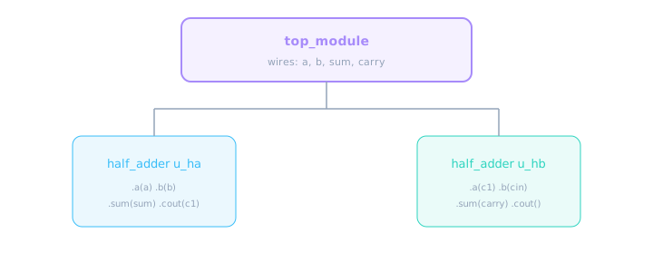
Parent declares wires; children connect via named port maps (.port(signal)).
module half_adder (
  input  wire a, b,
  output wire sum, cout
);
  assign sum  = a ^ b;
  assign cout = a & b;
endmodule

module full_adder (
  input  wire a, b, cin,
  output wire sum, cout
);
  wire s1, c1, c2;

  half_adder u_ha (.a(a),  .b(b),   .sum(s1),  .cout(c1));
  half_adder u_hb (.a(s1), .b(cin), .sum(sum), .cout(c2));
  assign cout = c1 | c2;
endmodule
Two connection styles exist:
- Named port map (preferred):
.port_name(wire_name)— order-independent, self-documenting. - Positional:
half_adder u_ha (a, b, s1, c1);— fragile if port order changes.
Instance names (u_ha) are required for simulation waveforms and synthesis reports. Always name your instances.
Hierarchical names — dot notation
In simulation and debug, you reference signals inside instances with hierarchical paths: top.child.grandchild.signal.
// In a testbench or $display / waveform viewer:
//   dut.u_core.u_alu.result
//   dut.u_core.clk
//
// SystemVerilog assertion example:
// assert property (@(posedge clk) dut.u_fifo.empty == 0);

module tb;
  reg  a, b, cin;
  wire sum, cout;

  full_adder dut (.a(a), .b(b), .cin(cin), .sum(sum), .cout(cout));

  initial begin
    a = 0; b = 0; cin = 0; #10;
    a = 1; b = 1; cin = 0; #10;
    // Waveform: expand dut → u_ha → internal wires
    $display("sum=%b cout=%b", sum, cout);
    $finish;
  end
endmodule
| Path segment | Meaning | Example |
|---|---|---|
| Module instance | A child block | dut.u_alu |
| Generate block | Array of instances | genblk[3].u_cell |
| Signal | Wire or reg inside | dut.u_fifo.count |
In GTKWave or your simulator GUI, the hierarchy tree mirrors the source structure. If you can't find a signal, check whether it's declared inside the right instance scope.
Your first complete DUT + testbench
A Device Under Test (DUT) is the design you're verifying. The testbench (TB) is a separate module that instantiates the DUT, drives inputs, and checks outputs. TB is not synthesized — it can use delays (#), $display, and $finish.
// --- DUT: synthesizable ---
module and_gate (
  input  wire a, b,
  output wire y
);
  assign y = a & b;
endmodule
// --- TB: simulation only ---
module and_gate_tb;
  reg  a, b;
  wire y;

  and_gate dut (.a(a), .b(b), .y(y));

  initial begin
    $dumpfile("and_gate.vcd");
    $dumpvars(0, and_gate_tb);
  end

  initial begin
    a = 0; b = 0; #10;
    if (y !== 0) $error("FAIL: 0&0");
    a = 1; b = 0; #10;
    if (y !== 0) $error("FAIL: 1&0");
    a = 1; b = 1; #10;
    if (y !== 1) $error("FAIL: 1&1");
    $display("All tests passed");
    $finish;
  end
endmodule
- DUT has only
input/outputports — no TB constructs - TB drives inputs with
reg(orlogicin SV) - TB connects to DUT outputs with
wire - Use
#delayonly in TB, never in synthesizable RTL
Parameters and generate preview
Modules can be parameterized — one RTL description, many sizes. You'll use this heavily for buses and counters.
module mux2 #(
  parameter WIDTH = 8
)(
  input  wire [WIDTH-1:0] a, b,
  input  wire             sel,
  output wire [WIDTH-1:0] y
);
  assign y = sel ? b : a;
endmodule

// Instantiate with override:
// mux2 #(.WIDTH(16)) u_mux (...);
Forgetting the #() when overriding parameters: mux2 #(.WIDTH(32)) u (...) not mux2(.WIDTH(32)).
File organization habits
Small designs: one file per module. Larger designs: group related modules, one module per file named after the module.
| File | Contains | Synthesized? |
|---|---|---|
and_gate.v | DUT only | Yes |
and_gate_tb.v | TB only | No |
top.v | Top + child instances | Yes |
defines.vh | `define macros | Preprocessed |
RTL engineers keep TB out of synthesis file lists. Your Makefile or tool script compiles DUT files for synth and adds TB only for sim.
🎯 What to remember
module/endmodulewraps every design unit; ports define the boundary.input= driven from outside;output= driven from inside.- Instantiate children with named port maps; use hierarchical paths for debug.
- DUT is synthesizable; TB is simulation-only with delays and checks.
- ANSI port style is the modern default — direction in the port list.