Physical Design (PD) — floorplan, place, route, timing overview
After synthesis, the design becomes geometry. Physical design places cells and routes wires on metal layers so the chip meets timing, power, and density rules. RTL authors who understand PD write friendlier RTL.
The PD playlist (simplified)
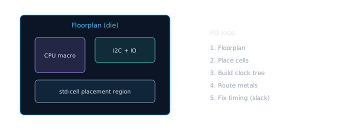
Physical design turns a netlist into geometry — wires have delay and congestion.
- Floorplan — die size, macro placement, IO rings, power grid sketch.
- Placement — standard cells find homes.
- Clock tree synthesis (CTS) — build a balanced clock network.
- Routing — connect pins with metal wires.
- Optimization / timing closure — iterate until paths meet constraints.
Each step — deeper
| Step | What happens | RTL impact |
|---|---|---|
| Floorplan | Die size, macro slots, power straps | IO-heavy blocks near pads |
| Placement | Cells placed in rows | Hierarchy guides locality |
| CTS | Clock tree balanced for skew | Fewer clock domains = simpler CTS |
| Routing | Metal layers connect pins | Wide buses → congestion |
| ECO | Late metal-only fixes | RTL change avoided if possible ($$$) |
Why wires matter
In advanced nodes, wire delay and congestion can dominate. A “perfect” RTL path can fail because two blocks were placed far apart.
Architecture + hierarchy influence PD. Giant flat modules are harder to floorplan than clean hierarchies.
Wire delay intuition
Gate delay was king at old nodes. Today, a signal may spend more time traveling on metal than switching a transistor. Long unregistered paths crossing the die are timing killers.
“It met timing in synthesis” — pre-layout estimates omit real wire RC. Post-route STA is the truth for ASIC.
Congestion
Too many wires in one region → router cannot finish → PD asks for RTL pipelining or floorplan change. Symptoms: high utilization + timing fail on unrelated paths.
What RTL can do to help PD
- Register outputs of large blocks (pipeline pressure valves)
- Avoid needless wide buses crossing the whole chip
- Keep clock domains intentional and documented
- Don’t create 50-level combo clouds “because it simulated”
You are not expected to run Innovus/ICC2 in this course. You are expected to stop writing RTL that fights physics.
RTL habit that helps PD: register block outputs so long combo paths do not span the die.
// Friendly for timing closure: register outputs of a block
module block_out_reg (
  input  wire       clk,
  input  wire       rst_n,
  input  wire [31:0] combo_result, // from heavy internal logic
  output reg  [31:0] block_q
);
  always @(posedge clk or negedge rst_n) begin
    if (!rst_n) block_q <= 32'd0;
    else        block_q <= combo_result;
  end
endmodule

// Why: PD can place this flop as a timing "pressure valve"
// between distant regions of the chip.
Pipelining example — 2-stage adder path
module pipelined_add (
  input  wire        clk, rst_n,
  input  wire [31:0] a, b,
  output wire [32:0] sum
);
  reg [31:0] a_r, b_r;
  reg [32:0] sum_r;

  always @(posedge clk or negedge rst_n) begin
    if (!rst_n) begin a_r <= 0; b_r <= 0; sum_r <= 0; end
    else begin
      a_r   <= a;           // stage 1: register inputs
      b_r   <= b;
      sum_r <= a_r + b_r;   // stage 2: add registered operands
    end
  end
  assign sum = sum_r;
endmodule
PD asks for “a pipeline flop on the CSR read path” — they need shorter combo delay after placement, not a lecture on Verilog.
Timing closure (vocabulary)
- Setup — data must be stable before the capturing edge (with margin).
- Hold — data must remain stable after the edge.
- Slack — how much margin you have (negative = fail).
Setup is “arrive before departure.” Hold is “don’t leave the platform too early and take the wrong suitcase.” Slack is how many minutes early you are.
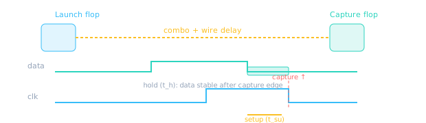
PD + STA prove every path has positive setup and hold slack.
How RTL hierarchy helps PD
- Placement regions: Synthesis preserves hierarchy; PD can guide blocks near related macros.
- Incremental closure: Fix timing block-by-block instead of flat 2M-instance chaos.
- Reuse: Verified I2C IP drops into next chip with known PD footprint.
“Setup vs hold?” — Setup = data too late before clock edge. Hold = data changes too soon after edge. Fix methods differ (pipeline vs buffer delay).
🎯 What to remember
- PD turns netlists into placed-and-routed geometry.
- Wire delay and congestion make hierarchy and pipelining matter.
- RTL choices affect how hard timing closure becomes.
- Next: sign-off checks and what tape-out means.