Why pipeline — throughput vs latency
Pipelining is the standard way to raise throughput without making every operation faster. You split long combinational work across stages separated by registers — each stage finishes in one clock, but the pipe can accept a new input every cycle once filled.
Latency = time for one item to traverse the pipe. Throughput = items completed per unit time. Pipelining usually increases throughput while latency per item stays the same or grows slightly.
Latency vs throughput — the formulas
Think of a datapath as N stages, each taking one clock period T. Without pipelining, one operation needs all stages in series:
| Metric | Non-pipelined (N stages) | Pipelined (N stages, steady state) |
|---|---|---|
| Latency per op | N × T | N × T (same path, plus register delay) |
| Throughput | 1 / (N×T) ops/cycle | 1 / T ops/cycle (one result/cycle) |
| Time to finish K ops | K × N × T | (N + K − 1) × T |
Non-pipelined: like one chef who chops, cooks, and plates before starting the next order. Pipelined: three chefs — each does one step; a new order enters every minute even though one plate still takes three minutes.
Non-pipelined: 12 cycles total.
Pipelined: 3-cycle latency per op, but 1 op/cycle throughput after fill. Total 6 cycles.
The third row in the table — time to finish K ops — is what architects quote in datasheets. For large K the fill and drain overhead (N−1 cycles each) vanishes, and pipelining wins by nearly a factor of N. For K=1 the pipelined design is strictly worse: you pay the same latency plus register overhead with no throughput gain.
CPI (cycles per instruction) measures how many clocks each instruction occupies the pipe on average. In a perfect pipe CPI → 1 even though latency is N cycles. Do not confuse CPI with latency — a 5-stage CPU can have CPI=1 and 5-cycle branch latency simultaneously.
Before vs after — pipeline diagram
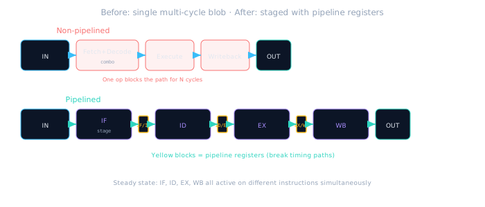
Pipeline registers turn one long path into N shorter paths — each stage meets timing at higher Fmax.
Each yellow register block is a timing boundary. Synthesis tools report critical path between registers, not across the whole datapath. That is why a 4-stage pipe at 200 MHz can beat a monolithic block stuck at 80 MHz — even if total register count doubles.
Fill, steady state, and drain
A pipeline is only at full throughput during steady state — when every stage holds a different operation. Before that you have a fill phase (pipe warming up) and after the last input you have a drain phase (pipe emptying). Neither phase achieves 1 op/cycle.
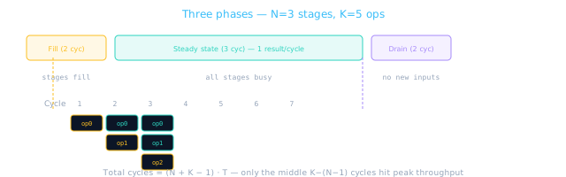
Burst workloads with small K spend a large fraction of time in fill/drain — profile before committing to a deep pipe.
Quoting "1 op/cycle" without mentioning warm-up misleads stakeholders. A DMA block that processes 4-word bursts will never reach steady state — calculate (N+K−1) explicitly for your real K.
In synthesis reports, compare achieved Fmax before and after pipelining on the same RTL at the same corner — the register overhead is real, but the shorter combo paths usually dominate.
Minimal pipeline register RTL
Every stage boundary is a register bank with an enable. When stalled, hold the register; when flushed, clear to a safe value.
// Generic pipeline register — IF/ID example
module pipe_if_id (
  input  wire        clk,
  input  wire        rst_n,
  input  wire        stall,   // hold current value
  input  wire        flush,   // squash bubble (branch mispredict)
  input  wire [31:0] pc_in,
  input  wire [31:0] instr_in,
  output reg  [31:0] pc_out,
  output reg  [31:0] instr_out
);
  always @(posedge clk or negedge rst_n) begin
    if (!rst_n) begin
      pc_out    <= 32'h0;
      instr_out <= 32'h00000013; // NOP (addi x0,x0,0)
    end else if (flush) begin
      pc_out    <= 32'h0;
      instr_out <= 32'h00000013;
    end else if (!stall) begin
      pc_out    <= pc_in;
      instr_out <= instr_in;
    end
    // else: stall — retain previous
  end
endmodule
// Count completed ops per cycle in simulation
reg [31:0] ops_done, cycles;
wire       valid_wb = wb_valid && !wb_stall;

always @(posedge clk or negedge rst_n) begin
  if (!rst_n) begin
    ops_done <= 0;
    cycles   <= 0;
  end else begin
    cycles <= cycles + 1;
    if (valid_wb) ops_done <= ops_done + 1;
  end
end
// Throughput ≈ ops_done / cycles (after warm-up)
// Rough stage delay budget (post-place) — aim for balance
// Stage   | Combo delay (ns) | At 200 MHz budget = 5.0 ns
// IF      | 1.8              | OK
// ID      | 2.1              | OK
// EX      | 4.9              | ← bottleneck; limits Fmax
// MEM     | 2.0              | OK
// WB      | 0.8              | OK
// Fix: split EX (shifter vs ALU) or predecode in ID — not more registers blindly
Pipeline registers cost flip-flops and routing. A 32-bit datapath with 4 boundaries adds roughly 4×32 = 128 FFs per lane, plus control fields. Justify that area against sustained ops/cycle — not against peak theoretical Fmax alone.
When pipelining helps — and when it hurts
The decision is workload-shaped. Ask two questions before inserting registers: (1) Is the block busy most cycles? (2) Can operands arrive back-to-back without long idle gaps? If both are yes, pipelining is likely worth the hazard-control tax in later lessons.
Helps
Steady stream of independent work; long combo paths; need higher Fmax; batch processing (K ≫ N).
Hurts
Single-shot latency-critical paths; heavy data dependencies; frequent flushes; area/power budget tight.
Diminishing returns
Very deep pipes → branch penalty, hazard logic, register overhead. Sweet spot is usually 3–5 stages for simple blocks.
| Scenario | Pipeline verdict | Why |
|---|---|---|
| Streaming MAC in DSP | Strong yes | Continuous operands; throughput = revenue |
| Config register read | No | One access every ms — latency matters, not IPC |
| CPU core | Yes (with hazards) | IPC near 1 possible; hazard logic pays off |
| Deeply nested branches | Marginal | Flush bubbles eat throughput gains |
Do not pipeline just to "look like a CPU." If your block runs once per 1000 cycles, pipeline registers add latency and area with zero throughput benefit. Profile first: is the path always busy?
Timing budget — why Fmax rises
Critical path without pipeline: Tcrit = tIF + tID + tEX + tWB. With registers between stages: Tcrit = max(tIF, tID, tEX, tWB) + treg. You trade register delay for the ability to clock faster.
Rule of thumb: If each stage is balanced (~equal delay), pipelining nearly multiplies throughput by N. Unbalanced stages leave the slowest stage as the bottleneck — optimize that stage first.
Register clock-to-Q and setup time (treg) eat into every stage budget. Deep pipelines raise Fmax but also raise hazard penalty (more in-flight ops per branch). The sweet spot is usually the shallowest pipe that closes timing at the target frequency.
"Does pipelining reduce latency?" — Correct answer: no for a single operation; it may even increase latency slightly due to register delay. Pipelining increases throughput and enables higher clock by shortening the combinational path per stage.
Pipeline design checklist
- Latency requirement documented (single-op vs sustained throughput)
- Stage boundaries drawn — one major function per stage
- Pipeline registers have stall, flush, and reset behavior
- Throughput formula checked for expected K (batch size)
- Area cost of N−1 register banks justified by workload
- Fill/drain overhead calculated for actual batch size K
Worked example — DSP MAC pipe
A multiply-accumulate unit with 3 stages (multiply → accumulate → round) processing a streaming audio buffer illustrates the throughput win:
| Design | K=1024 samples | Steady-state rate |
|---|---|---|
| Monolithic MAC (3-cycle combo) | 3072 cycles | 0.33 samples/cycle |
| 3-stage pipeline | 1024 + 2 = 1026 cycles | 1 sample/cycle |
The pipeline saves ~2000 cycles on this burst — but the first sample still exits after 3 cycles (latency unchanged). Audio drivers care about sustained rate; interrupt handlers care about single-op latency. Document which metric your block optimizes.
// 3-stage MAC — sample streams in every cycle after fill
// Stage 1: a * b  → prod_reg
// Stage 2: prod + acc → acc_reg  (acc feedback from WB optional)
// Stage 3: round/sat → out_reg
// valid_out asserts 1/cycle in steady state when valid_in is continuous
🎯 What to remember
- Latency = end-to-end time per item; throughput = items per cycle in steady state.
- Pipelining raises throughput to ~1 op/cycle without shrinking per-stage work.
- Pipeline registers break timing paths — often the real reason Fmax improves.
- Skip pipelining when work is rare, dependencies dominate, or flushes are constant.
- Fill and drain matter for small K — always compute (N + K − 1), not just N.