Timing diagram literacy — how to read waveforms
Waveforms are the RTL engineer’s X-ray. If you cannot read a timing diagram, you cannot debug. This lesson teaches the visual language: edges, levels, don’t-care, buses, and cause→effect.
Look at a wave and predict the next sample — then explain why a bug appears one cycle late.
Anatomy of a timing diagram
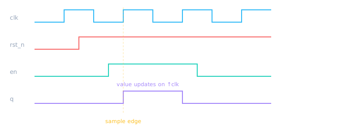
Time flows left→right. Vertical dashed lines mark interesting clock edges.
| Symbol / look | Meaning |
|---|---|
| High / low flat line | Logic 1 / 0 stable |
| Vertical transition | Value change |
| X or hashed | Unknown / conflict |
| Z (often mid) | High-impedance (bus idle) |
| Bus hex label | Multi-bit value at that time |
Combo vs registered delay on waves
module wave_lab (
  input  wire clk, rst_n,
  input  wire a, b,
  output wire y_combo,
  output reg  y_seq
);
  assign y_combo = a & b;                 // immediate (combo)

  always @(posedge clk or negedge rst_n) begin
    if (!rst_n) y_seq <= 1'b0;
    else        y_seq <= a & b;           // delayed one clock
  end
endmodule
module tb_wave_lab;
  reg clk=0, rst_n=0, a=0, b=0;
  wire y_combo; reg y_seq;
  // Note: instantiate wave_lab in simulator; dump waves
  always #5 clk = ~clk;
  initial begin
    rst_n=0; #20; rst_n=1;
    a=1; b=0; #30;
    b=1; #40;          // watch y_combo vs y_seq
    $finish;
  end
endmodule
▶ Compare combo vs seq on waves
Combo glitches — spikes that flops ignore
Combinational outputs can glitch (briefly go wrong) while inputs settle. A registered output samples only on the clock edge — after combo has stabilized (setup time). That is why FSM outputs are often registered.
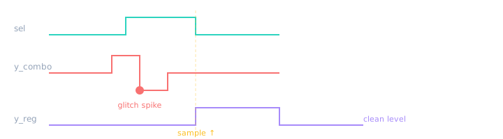
Mux/select changes can make combo output bounce; the flop sees only the settled value at the edge.
Using a combo output to clock or latch something else → glitches become real logic events. Register before driving critical control.
Generating waveforms — $dumpvars & VCD mental model
Simulation writes a VCD (Value Change Dump) file — a time-ordered log of signal transitions. Viewers (GTKWave, sim GUIs) reconstruct the waves you draw on paper.
- Hierarchy: VCD stores
top.u_dut.clkstyle paths — scope matters when tracing. - Time steps: Each line is “at time T, signal S became value V.”
- Dump control:
$dumpfilenames the file;$dumpvarschooses depth (0=only args, 1=one level down, etc.). - Read waves: Zoom to the first wrong transition; correlate with
$displaytimestamps.
| System task | Purpose |
|---|---|
$dumpfile("waves.vcd") | Open/create VCD output file |
$dumpvars(0, tb) | Dump only tb signals |
$dumpvars(1, tb.dut) | Dump dut + one level of children |
$dumpoff / $dumpon | Pause/resume logging (smaller files) |
module tb_dumpvars;
  reg clk = 0;
  always #5 clk = ~clk;

  wave_lab u_dut (.clk(clk), .rst_n(1'b1), .a(1'b1), .b(1'b0),
                  .y_combo(), .y_seq());

  initial begin
    $dumpfile("wave_lab.vcd");       // 1) pick filename
    $dumpvars(0, tb_dumpvars);       // 2) dump this module
    $dumpvars(1, u_dut);             // 3) dump DUT + ports
    #100;
    $display("t=%0t done", $time);    // correlate text ↔ VCD time
    $finish;
  end
endmodule
// Mental model: VCD = {time, signal, value} rows → viewer draws horizontal segments
Try it: Run in simulator, download/open the VCD if supported, or watch the built-in wave pane. Toggle a/b and confirm y_combo moves immediately while y_seq lags one clock.
Debug method (cause → effect)
- Find the first wrong signal (not the last symptom).
- Check reset was released and clock is toggling.
- Ask: should this signal be combo or registered?
- Walk one cycle backward: what was D at the previous edge?
- Confirm enables, stalls, and FSM state.
“Walk me through this waveform” — narrate clock → reset → control → data. Silence while staring is a fail; structured narration is a pass.
Handshake wave (preview)
Valid/ready: data transfers only when both are high — Module 6 deep dive.
🎯 What to remember
- Waves show time causality — read left to right, edge by edge.
- Combo moves immediately; flops move on clock edges.
- Combo glitches are normal — register before critical control.
$dumpfile+$dumpvars→ VCD → waveform viewer.- Debug the first mismatch, not the last.
- Next: FPGA vs ASIC — same RTL, different constraints.