RTL Design — where you will live in this course
RTL design is the craft of describing digital hardware in a hardware description language so tools can simulate it and later implement it. This is your home base for the rest of the course.
Register-Transfer Level — you describe how data moves between registers each clock, and what combo logic sits between them.
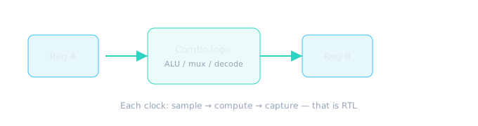
Register-Transfer Level = describe how data moves between flops each cycle.
A day in the life (realistic)
- Read a micro-spec / ticket for a block.
- Sketch FSM or datapath on paper.
- Code Verilog; keep synthesizable style.
- Write or extend a testbench; run waves.
- Run lint; fix latch / width / clock issues.
- Send for peer review; address comments.
- Hand to verification / synthesis with known open issues listed.
You are both author and first QA. Shipping untested RTL is like publishing a book without spellcheck.
Daily workflow — deeper cut
| Activity | Typical time | Output |
|---|---|---|
| Read spec / attend standup | 30–60 min | Clarified requirements, blockers listed |
| Code + local sim | 3–5 hrs | RTL diff + passing unit TB |
| Debug waves | 1–3 hrs | Root cause + fix or bug filed |
| Review (give/receive) | 1–2 hrs | Comments addressed in next commit |
| Lint / CDC / synthesis preview | 30 min | Clean reports or waiver request |
Collaboration map
- DV: You provide RTL + micro-arch doc; they scale tests. Agree on CSR golden model early.
- PD: You register outputs and document clocks; they ask for pipeline stages on long paths.
- DFT: You avoid latches and document async resets; they insert scan and ask for test mode muxes.
- Software: Register map is ABI — changing bit positions without notice breaks firmware.
End standups with “open issues” — not just “still coding.” List: lint waivers pending, CDC review needed, TB not updated for M4.
Example of clean, synthesizable style you will practice — a loadable counter:
module load_counter #(
  parameter WIDTH = 8
)(
  input  wire             clk,
  input  wire             rst_n,
  input  wire             load,
  input  wire             en,
  input  wire [WIDTH-1:0] din,
  output reg  [WIDTH-1:0] count
);
  always @(posedge clk or negedge rst_n) begin
    if (!rst_n)
      count <= {WIDTH{1'b0}};
    else if (load)
      count <= din;
    else if (en)
      count <= count + 1'b1;
  end
endmodule
Combo vs sequential — two coding styles
// COMBO: always @(*) or assign — no clock, updates when inputs change
assign sum = a + b;

// SEQ: always @(posedge clk) — state updates only on clock edge
always @(posedge clk or negedge rst_n)
  if (!rst_n) q <= 1'b0;
  else        q <= d;
FSM snippet (synthesizable two-process style)
module fsm_two_process (
  input  wire clk, rst_n, go,
  output reg  busy
);
  localparam IDLE = 1'b0, RUN = 1'b1;
  reg state, next;

  always @(posedge clk or negedge rst_n)
    if (!rst_n) state <= IDLE;
    else        state <= next;

  always @(*) begin
    next = state;
    busy = 1'b0;
    case (state)
      IDLE: if (go) next = RUN;
      RUN:  begin busy = 1'b1; next = IDLE; end
      default: next = IDLE;
    endcase
  end
endmodule
What “good RTL” optimizes for
Clarity
Teammates understand intent without archaeology.
Synthesizability
Maps cleanly to flops and gates.
Timing friendliness
Avoids accidental mega-combo clouds.
Verifiability
Observable, reset-clean, asserts possible.
Coding standards highlights
- One module per file; module name = file name
- Non-blocking
<=in sequential blocks; blocking=in combo - Full case / default in FSMs — no inferred latches
- Explicit widths on literals (
8'd0not bare0) - Reset strategy documented (sync vs async, active level)
- No delays (
#10) in synthesizable RTL
Review-ready checklist
- Spec MUST lines traced in header comment
- Unit TB passes; waves captured for main scenario
- Lint clean or waivers justified
- No TODO on critical paths without ticket number
- Register map matches architecture doc
“What makes RTL reviewable?” — Mention separation of combo/seq, FSM structure, reset, and tests included in the PR.
Your tools in this course
- Primary: EcrioniX Verilog Simulator for edit → run → waves.
- Mind tools: timing diagrams, state diagrams, checklists from Lesson 0.3.
- Later: lint/CDC/timing thinking in Module 9 (concepts first; tools second).
What RTL is NOT
- Not a software program that “runs line by line” on a CPU (simulation looks sequential; hardware is parallel).
- Not the final gates — synthesis decides many library cells.
- Not complete without verification evidence.
Mindset shift: you describe hardware structure and timed behavior, not algorithms in the software sense alone.
Why RTL quality ripples through the flow
| RTL habit | Who benefits |
|---|---|
| Registered block outputs | PD — timing closure |
| Clean FSM + full case | DFT — scan insertion |
| Observable CSR status bits | DV — self-checking TB |
| Documented reset values | FW — driver init sequence |
“I’ll clean it up after it works” — cleanup rarely happens before tape-out pressure. Write review-ready RTL on the first commit.
🎯 What to remember
- RTL describes register transfers and combo logic between clocks.
- Daily loop: specify → code → simulate → lint → review.
- Clarity + synthesizability + verifiability beat cleverness.
- Next: why verification is not optional.